Thanks Crash
Is the wiring for TDIF different from AES?
DIO8 TDIF
19 posts
• Page 2 of 2 • 1, 2
Re: DIO8 TDIF
![]() by Carlo » Tue Aug 04, 2015 1:57 pm
by Carlo » Tue Aug 04, 2015 1:57 pm
If I have seen further it is only by standing on the shoulders of giants........
-

Carlo - Premium Member

- Posts: 431
- Joined: Sat Jan 15, 2011 11:40 pm
- Location: EU
Re: DIO8 TDIF
![]() by Crash » Tue Aug 04, 2015 2:12 pm
by Crash » Tue Aug 04, 2015 2:12 pm
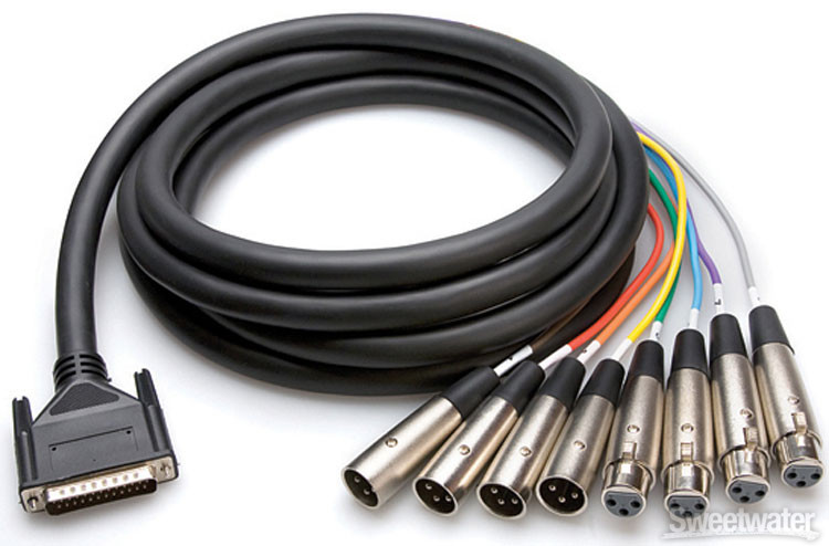
This what the cable looks like that I built.

It has been years since I built them so my memory is a bit fuzzy but I think this is the pinout I used. Maybe you can compare it to the card pin out and see if it matches. It would be that one or the one on the below I would think.
-

Crash - Premium Member
- Posts: 1282
- Joined: Fri Nov 21, 2008 10:05 pm
Re: DIO8 TDIF
![]() by Bruce Graham » Tue Aug 04, 2015 3:34 pm
by Bruce Graham » Tue Aug 04, 2015 3:34 pm
Hi Carlo & Crash;
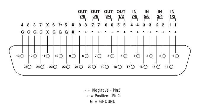
I believe the upper drawing is the analog standard pin-out used by MOST suppliers.
The lower one I THINK is the standard for the YAMAHA digital protocol, although I am not 100% sure. On the HOSA website they also call it the AES/EBU Pinout. I have been trying to find what the standards are in order to answer Carlo's origanal question, and finding conflicting information.
I do know that Protools uses the Analog pin-out for all it's db25 pin standards and just changes the XLR connectors. which makes in cheaper in design and build but means you can not use their cables with any other standard other than analog.
To that end I am still searching for the answer to the Carlo's question. Mackie's d8b manual's, from what I have read, only supply the analog pin-out. No AES/EBU or TDIF.
Here is an article I found on the HOSA website that MAY answer the question. http://hosatech.com/company-blog/db-25-enigma/
Hope this helps.
I will be gone until mid September and will catch up when I return.
Cheers
Bruce
- Bruce Graham
- Premium Member
- Posts: 717
- Joined: Tue Mar 15, 2011 12:02 am
- Location: Walkerton, Ontario, Canada
Re: DIO8 TDIF
![]() by anyhorizon » Tue Aug 04, 2015 5:10 pm
by anyhorizon » Tue Aug 04, 2015 5:10 pm
Just as a matter of mentioning, how stupid is the pin designation on the lower diagram?
Peter
Peter
In the scheme of things, there isn't one... just chaos.
-

anyhorizon - Premium Member
- Posts: 1069
- Joined: Fri Nov 21, 2008 9:36 pm
- Location: Down under or up over, depending on where in space you are.
Re: DIO8 TDIF
![]() by Crash » Tue Aug 04, 2015 6:14 pm
by Crash » Tue Aug 04, 2015 6:14 pm
Bruce Graham wrote:Hi Carlo & Crash;
I believe the upper drawing is the analog standard pin-out used by MOST suppliers.
Look at the very top row of info on the upper diagram. That shows the breakout side of the 4 male and female xlrs. I am fairly certain that was the Tascam pinout. It looks like yout typical analog pinout of the dsub but I don't think it is.
-
Crash - Premium Member
- Posts: 1282
- Joined: Fri Nov 21, 2008 10:05 pm
Re: DIO8 TDIF
![]() by anyhorizon » Wed Aug 05, 2015 12:05 am
by anyhorizon » Wed Aug 05, 2015 12:05 am
I was merely observing that if you used multi core, the location of the grounds is a pain in terms of soldering in the lower pin out diagram.
Peter
Peter
In the scheme of things, there isn't one... just chaos.
-
anyhorizon - Premium Member
- Posts: 1069
- Joined: Fri Nov 21, 2008 9:36 pm
- Location: Down under or up over, depending on where in space you are.
Re: DIO8 TDIF
![]() by Bruce Graham » Wed Aug 05, 2015 5:34 am
by Bruce Graham » Wed Aug 05, 2015 5:34 am
Hey Crash;
I see what you are saying but that is a standard used by Protools and possibly others. I'm not sure about Tascam for TDIF.
Can you get a part number for that cable? That may help to identify what manufacturer the cable was made for.
It appears that different Manufacture choose what pin-out they want. I'm just trying to get to the bottom of what the pin-out IS for TDIF. Just trying to make sure.
I have TDIF db25 male to db25 male that are foe use with the TDIF cards from Mackie. They work!
I have tried using a pair of what was AES db25 to XLR-3 (4 Male, 4 Female) and joined them XLR to XLR and that did not work. I gender changed some of them around trying to find something that worked and could not get anything to work.
I wish I could find the pin-out that Tascam is calling TDIF!
Hey Peter;
I agree with you regarding the soldering in that manner for the lower drawing. Who thought of that? It is not the easiest to do. I have made many Analog db25 to db25 and to XLR, and only a couple of the ones like the lower drawing. I hope to never have to do them again. It was not easy!.
Cheers
Bruce
- Bruce Graham
- Premium Member
- Posts: 717
- Joined: Tue Mar 15, 2011 12:02 am
- Location: Walkerton, Ontario, Canada
Re: DIO8 TDIF
![]() by Carlo » Wed Aug 05, 2015 12:15 pm
by Carlo » Wed Aug 05, 2015 12:15 pm
thanks for the suggestion and help...
REgards
Carlo
REgards
Carlo
If I have seen further it is only by standing on the shoulders of giants........
-
Carlo - Premium Member
- Posts: 431
- Joined: Sat Jan 15, 2011 11:40 pm
- Location: EU
Re: DIO8 TDIF
![]() by Crash » Wed Aug 05, 2015 3:37 pm
by Crash » Wed Aug 05, 2015 3:37 pm
It is confusing, looks like I was mistaken.
http://mackie.com/products/digitalxbus/ ... ctions.pdf
Page 47
http://mackie.com/products/digitalxbus/ ... ctions.pdf
Page 47
-
Crash - Premium Member
- Posts: 1282
- Joined: Fri Nov 21, 2008 10:05 pm
19 posts
• Page 2 of 2 • 1, 2
Who is online
Users browsing this forum: No registered users and 1 guest
Powered by phpBB© 2000, 2002, 2005, 2007 phpBB Group