Hi Carlo & Crash;
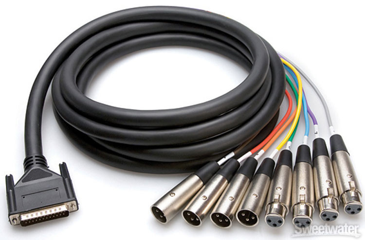
I believe the upper drawing is the analog standard pin-out used by MOST suppliers.
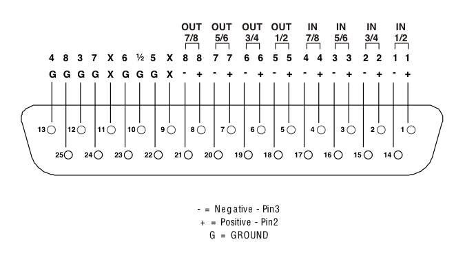
The lower one I THINK is the standard for the YAMAHA digital protocol, although I am not 100% sure. On the HOSA website they also call it the AES/EBU Pinout. I have been trying to find what the standards are in order to answer Carlo's origanal question, and finding conflicting information.
I do know that Protools uses the Analog pin-out for all it's db25 pin standards and just changes the XLR connectors. which makes in cheaper in design and build but means you can not use their cables with any other standard other than analog.
To that end I am still searching for the answer to the Carlo's question. Mackie's d8b manual's, from what I have read, only supply the analog pin-out. No AES/EBU or TDIF.
Here is an article I found on the HOSA website that MAY answer the question.
http://hosatech.com/company-blog/db-25-enigma/Hope this helps.
I will be gone until mid September and will catch up when I return.
Cheers
Bruce