Change font size   Print view

CPU / Power Supply

Discussion board for Mackie's d8b Digital Console users.

CPU / Power Supply

Postby doktor1360 » Fri Dec 31, 2021 3:54 am

I recently had the opportunity to purchase another D8B, essentially for a song (~ $350 including shipping). I don't know if anyone is familiar, but it belonged to Malcolm Cecil - renowned British jazz bassist and synth tech pioneer from back in the day. It was a backup unit based on the condition (1 of the 2 the estate sold), the console is almost factory floor pristine. The cpu host, not so much... it has the older motherboard rack case (different rear panels), but it's pretty clear whoever was servicing this was doing upgrades. It has the newer motherboard, cpu and RAM... but still has the floppy & hdd units w/ the v3.0 OS imaged on the drive. It boots to a point where the v3.0 splash screen displays and just hangs... which is the purpose of this posting.

I actually took my current #1 cpu, replaced the 4GB cf card with a blank and proceeded to seamlessly install the v5.1 OS/service pack with the new console attached... eliminating it from the equation. So, directly implicating the power supply half of the cpu host 'guts'. There's a thread here with a ton of info regarding the subject (RJH's reconstruction in particular) that I haven't followed too closely, my bad. That's due to being up to my arse in my own alligators, a good bit of that is what is driving this post. So, I skimmed cursorily thru that and a lot the exchange is really good, and accurate I might add. So I'm kinda walking on the shoulders of giants here. There is however also what I see as some 'mis-information' per-se, not maliciously stated but perhaps most likely misunderstood. So I started tearing into the service manual, looking at block diagrams, signal flow and the schematics. Just like the old days... LOL

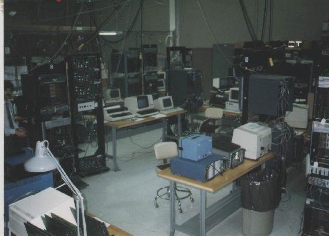
I'll quickly segue here to just provide a little of my own background - in the 80's thru the early 90's I worked as a technician (read Lab Rat) in the R&D dept of a very large data communications manufacturer. This also included power supplies, linear and switching... building, testing (hi-potting), etc. I've included a coupla links to OLD pictures - one is the desk of the power supply lead engineer, if you can see it. The other, is the lab where shit just got done. BERT's (bit error rate testers), protocol analyzers, all manner of test and diagnostic gear... home for me for almost 12+ yrs. But again, I digress a bit...

http://www.geocities.ws/mluczak.geo/infotron/images/pv_cube.jpg
http://www.geocities.ws/mluczak.geo/infotron/images/infostream_lab.jpg

So I want to address some points, and I'm gonna allow myself the liberty of taking a 50000 ft view of it all, drill down and see what's what. Lets start from a very basic, simplistic subsystem break down - there's a standard AT power supply (OEM Sparkle), and the rest of the assembly. I'm actually focusing on the page(s) in the schematics regarding the 'Linear Power Supply'. Um, OK... that's accurate to a degree, but I think I'd personally define that as the +/-16VDC and +48VDC linear supplies, and the interface to the remotely sensed +5VDC (OEM Astec) power supply.

Semantics? Not to a geek, sorry... lets break this down from the AC mains to the BFC cable assembly providing the conduit for console voltages - it's all that cable does, albeit a very critical component. We have 3 separate subsystems here to consider - 1) standard pc power supply, 2) the transformer and 3) the switch mode circuitry (Astec supply). Now, let's have a look at the power distribution board schematic, and it's clearly evident the they're isolated from each other, the on/off switch from the AC plug (rear main) with fuses. It doesn't do much, but what it does is save a whole lotta heartache should something happen externally.

The computer supply is self descriptive, wherein it provides +5VDC & +12VDC to the motherboard and computer peripherals. However, it also provides a direct +12VDC tap to the Linear Power Supply board (important). Looking on the linear power supply schematic on the right side of the document, you can see J2 & J200 - this is where electrically you can see the transfer take place. We're also relying on the fuse protecting the computer power supply here as well. The 'jumper' to the linear supply board is nothing more than a simple molex connector provided by the power supply, that's electrically connected to the adjacent 'birdpost' jumpered jack connector. The +12VDC is then electrically wired directly into the BFC cable assembly for delivery to the console.

Next in line is the transformer (coil) used by the linear power supply board in generating +/-16VDC & +48VDC supply voltages for the console. It receives 120VAC on the primary, and steps the secondary voltage(s) down according to the winding specs. The secondary has two stepped down voltage leads... there's a center-tapped [ground] set and a 2-wire set providing these voltages to the individual linear supplies. They're both inline fused to protect each from shorting out the other in the event of damaging electrical activity. The voltages for both are then diode rectified and 'smoothed' in their respective circuits discrete component layout, essentially voltages set and clamped to their engineered values (+/-16VDC & +48VDC respectively). The +48VDC supply essentially amplifies and regulates the supplied AC voltage via 2 TIP29C NPN power transistors in series to the +48VDC phantom power spec. The +/-16VDC supplies use LM317T (+) and LM337T (-) voltage regulators respectively to deliver a consistent voltage to their supply rails and dedicated analog ground reference. Looking at the 'linear power supply' board schematic, you can see the output of each and to the right bottom of diagram see the 5-pin J3... this is used for delivering the voltages and dedicated analog ground signals to the BFC cable assembly to be used in the console audio purposes. I haven't actually taken the time yet and worked the numbers according to the component values of each supply to determine voltages at various points in the circuitry, but clearly based on these values these supply circuits are a custom one-off design by Mackie engineers specifically for this piece of hardware. I personally think that due to the fact they're discreet electronic circuits that can be repaired by replacing the parts, good care should be taken preserving them. Any techie-type with soldering skills can handle it, this board is of an industrial-type thru hole design facilitating repairs.

Which leaves the +5VDC switched, remotely sensed power supply (OEM Astec)... on the upper right of the schematic diagram, this supply interface is clearly set off in it's own box indicating it's an abstraction... it's not actually part of the linear supply board itself. It receives it's (fused) AC feed from the power distribution board, and outputs a switched +5VDC and digital ground reference point. The voltage is delivered to two spade connectors (J5 & J6), and the remote sense is monitored thru a 2 pin connector (J4). Both voltage and sensing is then routed to the BFC cable via J20 to the console.

It would really be advantageous to have some test points established for these schematics - in other words with a properly working power supply, at what point(s) in the circuitry what measured voltages can be expected to be seen on a DVM. Just geeking again, I was kinda surprised when I didn't see these indicated... most of my industry exposure experience dictated things.

I'll continue this with another post in a day or three... I've actually got some points on integrating newer hardware, or at least more accessible long term. I just don't have my thoughts anywhere near organized right now...

Any ideas, thoughts, input, constructive criticism is greatly appreciated... and of course I stand corrected if any of this proves to be incorrect - but that would be the whole point of this exercise as it is.

Thanx in advance, and apologies to anyone's wasted bandwidth on this long-winded discourse...

Stay tuned for more...

\m/ ;)
Last edited by doktor1360 on Sat Jan 01, 2022 6:23 pm, edited 2 times in total.
--
Dok

"Too many guitars is just about right..." - [Anonymous Player]
User avatar
doktor1360
Premium Member
Premium Member
 
Posts: 467
Joined: Fri Mar 22, 2013 3:33 pm
Location: Marietta 30062, GA, United States

Re: CPU / Power Supply

Postby captainamerica » Fri Dec 31, 2021 5:54 am

looks like you not only have the smarts, drive, tech experience, and energy ...but also patience my friend. I will watch from the sideline for now. I am deep in tritone substitutions and chord voicing these days :) Good luck and Happy New Year
DAW: Genelec 8341,MacStudio, QuantumTB, Faderport16, DP, LogicProX, ProTools.BackupDAW:d8B, MacPro 2008 2xQuad-Core, MOTU (2408)LegacyDAW: A2000, Picasso II, Blizzard 68060@50 MHz|3xAD516 SunRize cards|HydraNexus Amiganet Ethernet.
User avatar
captainamerica
Premium Member
Premium Member
 
Posts: 338
Joined: Thu Nov 27, 2008 5:45 pm
Location: Boston, MA (org. from Montreal, Canada)

Re: CPU / Power Supply

Postby Jondav1120 » Sat Jan 01, 2022 11:43 am

Hi Doc,

And thanks for an excellent overview of the operation of the power supply.
Now, let's have a look at the power distribution board schematic, and it's clearly evident the they're isolated from each other

From the perspective of the circuit diagrams, I absolutely agree with this comment. There appears to be no connection between them at all...However, as I believe RJH found with his power supply and Ralph with the Probox, when replacing the power supplies on the D8B it is neccesary to link the mgnd (Motor Ground) and the dgnd (Digital ground) to get the faders and Vpots to work. This is because the 5v regulated supplies for the motor control and Vpot circuitry are derived from the 12V supply but referenced to the 5V ground. With no connection between the two grounds the 5V supply is effectively floating relative to the 12V ground. There are several of these regulators, one on each of the fader boards, one on each of the control surfaces, and another on the brain board. The fader board ones supply the D/A convertors, the fader itself and the associated circuitry. The one on the brain board supplies the A/D convertor, and the ones on the control surface boards supply the Vpot circuitry.
From memory, I think Ralph sugested linking the grounds together on the back of the power distribution board within the console.
I have no idea where this link between the two ground points is located when using the Mackie power supply/cpu, but it must be there. Maybe it depends on the ground of the 5V (Astec) supply being internally connected to the chassis of the Astec supply and then to the cpu chassis?

Regards

John
Jondav1120
Registered user
 
Posts: 150
Joined: Sat Jan 07, 2017 11:51 pm
Location: Surrey, UK

Re: CPU / Power Supply

Postby doktor1360 » Sat Jan 01, 2022 9:12 pm

Jondav1120 wrote:Hi Doc,

From the perspective of the circuit diagrams, I absolutely agree with this comment. There appears to be no connection between them at all...However, as I believe RJH found with his power supply and Ralph with the Probox, when replacing the power supplies on the D8B it is necessary to link the mgnd (Motor Ground) and the dgnd (Digital ground) to get the faders and Vpots to work. This is because the 5v regulated supplies for the motor control and Vpot circuitry are derived from the 12V supply but referenced to the 5V ground. With no connection between the two grounds the 5V supply is effectively floating relative to the 12V ground. There are several of these regulators, one on each of the fader boards, one on each of the control surfaces, and another on the brain board. The fader board ones supply the D/A convertors, the fader itself and the associated circuitry. The one on the brain board supplies the A/D convertor, and the ones on the control surface boards supply the Vpot circuitry.

From memory, I think Ralph suggested linking the grounds together on the back of the power distribution board within the console.

I have no idea where this link between the two ground points is located when using the Mackie power supply/cpu, but it must be there. Maybe it depends on the ground of the 5V (Astec) supply being internally connected to the chassis of the Astec supply and then to the cpu chassis?


RJH_MUSIC wrote:the d8b console needs 5 voltages to work;

+5 VDC, +12 VDC, - Lights potentiometers, disk drives
+16 VDC, -16 VDC, - Fader Motors
+48 VDC , - Phantom Power

The PSU Power supply provides all the power voltages needed for the motherboard and supplies the +12 VDC to the Linear Supply board which in turn is routed directly to the BFC (2 purple, 2 yellow wires). The LPS-152 power supply supplies +5 and +5 sense to the Linear Power Supply board which is sent out the BFC (4 orange 1 orange white, 4 black 1 black white wires). The Transformer inside the PSU supplies several voltages to the Linear Power Supply board including +60 and +24 VDC. The Linear Power supply board is a step down unit that contains the +/- 16 regulators, (the 2 components screwed to the heat sync). Here the voltage is rectified and sent out the BFC as +16, -16, +48 and common, (Red= +16, Blue= -16, Green= "AGrnd" and Brown= +48. This makes up the 18 pins in the BFC.


Kewlio, John... this is what I personally was sort of seeking from the various threads addressing this subject. I also found a particular post by RJH_MUSIC (above) that saved me a phone call to Electonetics.US to see if they even had the winding specs to that transformer, as the secondary tap values (+60 & +24 VAC) being important in the subsequent supply circuit(s). That's critical data in establishing voltage check points for triage purposes, it'll tie together the discrete component logic surrounding the NPN's and TIP29's respectively. After all, they're mostly 'amplifiers' at a certain level, so you can essentially expect to see various voltage divider networks helping configure the transistor circuits involved... the discrete's (resistors, caps [coupling & filter] and diode varieties), they all have their specific function, and component value, in the overall equation to ensure the voltage & current load specs are met or exceeded. All things considered from an engineering standpoint, that's what keeps us all running smoothly regardless of most anything going on outside the D8B host/console units themselves...

To address the ground issue, I'd have to agree. At some level, ground is ground, but to the electronics involved they need the appropriate 'reference'. The distribution board certainly appears to be the 'common' block for grounding, but it may have a good bit to do with the secondary side of the transformer being in the mix electrically. This article from Arrow Electonics is a fairly lay-level explanation with enuff meat for the techies among us (sub-section paragraphs 3 & 4) - it'll certainly does more justice than me going off for two or three long-winded paragraphs (LOL). Overall, I"d have to agree about some sort of common junction exists somewhere... I'll have to personally take a deeper dive on the various docs to make a further attempt at pin-pointing this 'enigma'...

https://www.arrow.com/en/research-and-events/articles/principles-of-grounding-for-mixed-signal-designs

Really valuable input, tho... I personally appreciate it, man!

To be continued...

\m/ 8-)
Last edited by doktor1360 on Mon Jan 03, 2022 6:55 pm, edited 2 times in total.
--
Dok

"Too many guitars is just about right..." - [Anonymous Player]
User avatar
doktor1360
Premium Member
Premium Member
 
Posts: 467
Joined: Fri Mar 22, 2013 3:33 pm
Location: Marietta 30062, GA, United States

Re: CPU / Power Supply

Postby doktor1360 » Sun Jan 02, 2022 4:35 pm

captainamerica wrote:looks like you not only have the smarts, drive, tech experience, and energy ...but also patience my friend. I will watch from the sideline for now. I am deep in tritone substitutions and chord voicing these days :) Good luck and Happy New Year

Hahaha...

Thanx a bunch for the kind words, Capt A... this is just what I've done over the years to 'pay the bills'... retired now, so this is a nice diversion (LOL)

I joke all the time with people when I hear things like that... "Appreciate it, but in truth I actually forgot more than most people know..." :D

Tritones n intervals... love the subject. I've been busy resuscitating my keyboard skills along side everything else. Reworking some guitar passages, trying different inversions n stuff on both... tonal experimenting, channeling my inner Kerry Livgren / Ken Hensley...

All just part of the fun, man... ;)

ALL the best... you and family have a Happy 2022 as well!

\m/ :)
--
Dok

"Too many guitars is just about right..." - [Anonymous Player]
User avatar
doktor1360
Premium Member
Premium Member
 
Posts: 467
Joined: Fri Mar 22, 2013 3:33 pm
Location: Marietta 30062, GA, United States

Re: CPU / Power Supply

Postby RJH_MUSIC » Wed Jan 05, 2022 6:43 pm

Pretty much spot on from what read. I had originally made a mistake in one of my posts but corrected it in my final build doc.

+5, +5 Sense Potentiometers, V Pots, LED's
+12 Drives, Motherboard, Fader power
+/- 16 Analog Circuits
+48 Phantom Power

Most important - If you are using original parts from d8b (all power supplies) there is no need to put a jumper between the mground and dground on the power distribution board located in the console. I also could not get the +5 sense to work properly. I used a switching power supply but when I connected the +5 sense outputs, the d8b would not boot up. once i disconnected that output, it booted up fine.

If you swap out transformer with another power supply, then you need to put a jumper where Ralph indicates on the power distribution board within the console. I believe all the grounds are tied together on the power distribution board that is in the CPU where all the fuses are located.
2 d8b's 5.1 OS all the plugins, Mackie 32.8 Bus, 2 iMAC 27", Apollo 8 Quad, Cubase 9, Logic Pro X, VEP 6, 4 TB of VSTi Libraries, 28 Roland, Yamaha & Korg Synths and Keyboards, NI Hardware and Software.. Plugins, Plugins, and the list goes on...
User avatar
RJH_MUSIC
Premium Member
Premium Member
 
Posts: 291
Joined: Fri Oct 26, 2012 4:24 pm
Location: Brookfield, CT

Re: CPU / Power Supply

Postby RJH_MUSIC » Wed Jan 05, 2022 6:45 pm

Who knows.... Maybe we will see a new OS for 2022....LOL
2 d8b's 5.1 OS all the plugins, Mackie 32.8 Bus, 2 iMAC 27", Apollo 8 Quad, Cubase 9, Logic Pro X, VEP 6, 4 TB of VSTi Libraries, 28 Roland, Yamaha & Korg Synths and Keyboards, NI Hardware and Software.. Plugins, Plugins, and the list goes on...
User avatar
RJH_MUSIC
Premium Member
Premium Member
 
Posts: 291
Joined: Fri Oct 26, 2012 4:24 pm
Location: Brookfield, CT

Re: CPU / Power Supply

Postby captainamerica » Wed Jan 05, 2022 7:27 pm

a new O/S...wow wouldn't that be nice!
DAW: Genelec 8341,MacStudio, QuantumTB, Faderport16, DP, LogicProX, ProTools.BackupDAW:d8B, MacPro 2008 2xQuad-Core, MOTU (2408)LegacyDAW: A2000, Picasso II, Blizzard 68060@50 MHz|3xAD516 SunRize cards|HydraNexus Amiganet Ethernet.
User avatar
captainamerica
Premium Member
Premium Member
 
Posts: 338
Joined: Thu Nov 27, 2008 5:45 pm
Location: Boston, MA (org. from Montreal, Canada)

Re: CPU / Power Supply

Postby doktor1360 » Wed Jan 05, 2022 8:18 pm

RJH_MUSIC wrote:Pretty much spot on from what read. I had originally made a mistake in one of my posts but corrected it in my final build doc.

+5, +5 Sense Potentiometers, V Pots, LED's
+12 Drives, Motherboard, Fader power
+/- 16 Analog Circuits
+48 Phantom Power

Most important - If you are using original parts from d8b (all power supplies) there is no need to put a jumper between the mground and dground on the power distribution board located in the console. I also could not get the +5 sense to work properly. I used a switching power supply but when I connected the +5 sense outputs, the d8b would not boot up. once i disconnected that output, it booted up fine.

If you swap out transformer with another power supply, then you need to put a jumper where Ralph indicates on the power distribution board within the console. I believe all the grounds are tied together on the power distribution board that is in the CPU where all the fuses are located.


I'd first like to thank you for pioneering that effort to rework the power supply 'bloc', and the really nice proto unit you produced. It should be noted that you tackling this saved anyone and everyone (including myself) a great deal of due diligence in this area... along with the obvious blood, sweat n tears. As I mentioned, I was personally walking on the shoulders of the giants that preceded my own efforts here... :geek:

That's an interesting point, regarding the remote sense. As I got to looking into this particular part of the supply voltage(s), I read up a bit on how remote sense is implemented. It's really a little sensing circuit that, for all intents and purposes, presents NO load to the supply voltages as it's such a high resistance value to the circuit. All it does is 'sense' changes in the load so the power supply circuitry can adjust things accordingly. The supply itself provides the 'sense' output terminals, the sense circuitry is provided by the supply itself (it's 'onboard'). In the case with the Astec LPS-152, they essentially jumper together the +5v output sense terminal with a ground reference that's then jumpered to the linear power supply board (J4 2-pin mini connector). I personally think this is ultimately provided in the event that the console is under such heavy usage that the amperage required begins to 'drag' the supply voltage down due to the load. It doesn't happen when it's remotely sensed, the supply adjusts under these adverse conditions. Designs are usually spec'd out at the engineering level, and those are usually the extremes that can be 'guaranteed' by by the manufacturer (Mackie/Loud). IMHO, again, I'd kinda seriously doubt anyone here has even approached that - but that's just a personal speculation...

As far as swapping out the transformer, for me, there's no compelling reason in reality. It does what it does, and it won't fail unless it's catastrophic.. the winding's shorting in either the primary or secondary. I actually prefer the simplicity, as it's doing nothing more than functionally providing the exact voltages on the secondary taps required by the +/-16vdc & +48vdc supplies respectively - it's just 'iron' *winks*. I'm sorta moving forward with the 'if it ain't broken, don't fix it' mentality and 'school of engineering'...

Again, thanx for all the input man... it's really eye-opening in a sense (no pun intended LOL) - and it's only gonna pay itself forward!

All the best, RJH!

\m/ ;)
--
Dok

"Too many guitars is just about right..." - [Anonymous Player]
User avatar
doktor1360
Premium Member
Premium Member
 
Posts: 467
Joined: Fri Mar 22, 2013 3:33 pm
Location: Marietta 30062, GA, United States

Re: CPU / Power Supply

Postby RJH_MUSIC » Fri Jan 07, 2022 5:59 pm

Thanks so much for the kind words, and yes it was a labor intense exercise. Glad it is behind me. And I agree, on the Sense discussion. It could be that the new power supply I used did not see any voltage drops and that could have caused the unit to pause and not boot up with it connected. I also agree with the transformed thoughts. My whole reason for wanting to get rid of it was so i could get rid of the Linear Power Supply Board, but n the end, that was not feasible. Maybe I
will conquer that in my next build.

Cheers
2 d8b's 5.1 OS all the plugins, Mackie 32.8 Bus, 2 iMAC 27", Apollo 8 Quad, Cubase 9, Logic Pro X, VEP 6, 4 TB of VSTi Libraries, 28 Roland, Yamaha & Korg Synths and Keyboards, NI Hardware and Software.. Plugins, Plugins, and the list goes on...
User avatar
RJH_MUSIC
Premium Member
Premium Member
 
Posts: 291
Joined: Fri Oct 26, 2012 4:24 pm
Location: Brookfield, CT

Next

Return to d8b Forum

Who is online

Users browsing this forum: No registered users and 20 guests