Change font size   Print view

3 Apogee Clock cards - solder issues in the same spot on all

Discussion board for Mackie's d8b Digital Console users.

3 Apogee Clock cards - solder issues in the same spot on all

Postby Y-my-R » Tue Sep 06, 2022 6:15 pm

So, after a myriad of other issues I had with the D8B, lately, this weekend, it would give me drop-outs, pops and clicks… during every complete run through a song, at least 4 or 5 tweater-threatening LOUD digital clicks/pops. That is, while it “claimed” to be properly synced to external word clock, and never looked like it lost the clock at any time (e.g. no questionmark briefly flashing on the display, etc.)

I ALWAYS run synced to an external word-clock generator, so my D8B is always running on external clock. Switching to internal clock seemed to work better, but this does me no good in the context of my system setup.

Anyway, when investigating what’s going on, I also looked at my Apogee Clock card, and found something interesting:

One of those yellow little components on the card, had come loose AGAIN!!

When I first got this particular card in the mail a few years ago, despite of it having been well packed and it having been in an anti-static bag, on arrival, THAT yellow component was loose in the bag, and had fallen off the clock card. When inspecting the other “yellow” components, I found that one other one had also separated at it’s solder spot.

I re-flowed that solder spot, and soldered the component back on that fell off (being careful about the orientation… luckily, I already had another clock card and could compare to it). The card worked with external clock as it should after that.

Now, it was THIS card, that I had already re-soldered, that had separated AGAIN, at the same spot.

I have 3 D8B systems in total (2 mostly for parts, but they sorta work), so I also have a total of 3 Apogee Clock cards. I meant to grab another one of those cards to install that, since I didn’t feel like soldering right there… and here’s the kicker:

ALL 3 CARDS HAD PROBLEMS WITH SOLDER SPOTS ON THE SAME COMPONENTS ON THE CARD.

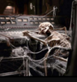
One of the cards was even missing that same component completely, without me ever noticing it (the card with the "extra cables" in the picture - that one has an added termination switch, to be able to turn word-clock termination off, if you need to daisy-chain other devices off of there... ignore - nothing to do with this issue).

On another card, the component was still there, but the contact had completely separated on one side (same as with the previously re-soldered card I currently used in the D8B).

This leads me to believe, that this is a SYSTEMIC issue, that likely impacts others as well, and not just me. I’m suspecting that that area gets particularly hot when the D8B is running for extended periods, and that the solder spot gets “almost” liquefied repeatedly and eventually gets brittle and breaks.

This may even be an explanation, why so many people have issues with running the D8B on external clock… I didn’t seem to have the same issues when switching to internal clock (the card with the missing component seems to work fine when running on internal clock)… so, maybe that component only gets used when running on external clock.

Anyway, I took pictures of 2 of my 3 Apogee clock cards. See below.

I marked the MOST problematic component that was bad on all 3 cards, but other ones of those yellow thingies, can also be loose (the one that was sent to me, had an additional “yellow" component loose… I’d just check them all)

I don’t need any help with any of this right now, so this is more of a suggestion to take a close look at your Apogee Clock cards, to check if all of those little yellow thingies are there, and to make sure that they look like they make good contact.

I’ve seen that these components are used a lot across the D8B, and start wondering if there may be more “aged” solder points across the circuit boards on my (and also other’s) D8B. This might explain even more of the strange wonkiness of these desks… but one thing I won’t do for sure, is re-flow ALL the solder spots inside the D8B… ain’t nobody got time for that!!

Anyway - hopefully this helps… maybe some of you could even run their desks on external clock, after re-flowing some of those clock-card solder spots :P

IMG_4779.JPG
Solder point had separated - same on a 3rd clock card I have
IMG_4779.JPG (Array KiB) Viewed 1096 times
Attachments
IMG_4781.JPG
IMG_4781.JPG (Array KiB) Viewed 1096 times
User avatar
Y-my-R
Premium Member
Premium Member
 
Posts: 525
Joined: Mon May 29, 2017 12:14 am
Location: Van Nuys, CA

Re: 3 Apogee Clock cards - solder issues in the same spot on

Postby Old School » Tue Sep 06, 2022 10:32 pm

Hi,
You are right about the issue being systemic. I pulled the apogee clock card from one of my D8B's and the yellow component was missing in that same spot. But good news, sort of, I pulled the card from my other D8B and the circuitry is totally different, no yellow components and no burned solder joints, so at some point they must have realized they had a problem and addressed the situation. I am including a photo of this different version.

Have a blessed day,
Mike
Attachments
Apogee card2.jpg
Apogee card2.jpg (Array KiB) Viewed 1091 times
Wanna make God laugh, ...Tell Him your plans
User avatar
Old School
Premium Member
Premium Member
 
Posts: 400
Joined: Thu Jun 16, 2011 8:42 pm
Location: Elm City NC

Re: 3 Apogee Clock cards - solder issues in the same spot on

Postby Y-my-R » Tue Sep 06, 2022 10:54 pm

Fascinating! So, it really seems to be true, that that's a common failure!

Thanks for sharing the pic of that other version of the card, Mike!

The circuit itself seems to be the same, and the version numbers of the chips and the revision number (B2) are also the same... it just seems that those little capacitors have a different color... but the same value (33 µ, 20 V).

Maybe those yellow ones had issues to have the solder adhere to them on the long term or something...

This makes me want to buy a handful of these capacitors to have them around, so I can replace them when they fall off... I don't know enough about electronics, to know what exactly I should be looking for... can someone point me in the right direction? Tantalum Capacitor at 33 µ/20 V... and what else... tolerances as good as available, I'd think, etc....?

What would be a good replacement component for these little yellow thingies?
User avatar
Y-my-R
Premium Member
Premium Member
 
Posts: 525
Joined: Mon May 29, 2017 12:14 am
Location: Van Nuys, CA

Re: 3 Apogee Clock cards - solder issues in the same spot on

Postby csp » Tue Sep 06, 2022 11:53 pm

Y-my-R,

For a change I can give some information !!!!!!

Tantalum Capacitors are polorised and the end with the line is Positive while the end with no line/mark is the Negative.

If possible always go for a higher voltage, The 20V is referenced to the "working voltage" and often (especially in power supplies) manufacturers use a capacitor/electrolitic that is just above the working voltage, whereas to be safe it should be at least 1.74 times the voltage. This is often a cause of problems with equipment that is manufactured in (say) counries where the mains voltage is 110V and they use an capacitor of about 200V working (often use one at about 250V for countries that have a 240V supply where thery will be selling their products),

BUT, those capacitors in the 240V country often fail after a relatively short time because using the 1.74 times principle the capacitors should be at least 417V working.

In the desk, the power supply to the various boards should be regulated and therefore fairly stable (irrespective of the country's mains supply) and the supply to the boards should be DC voltage (capacitors work on AC voltage --- they pass AC voltage , but block DC voltage) and should be fairly stable, but if (say) the voltage at the point of the capacitor is very close to the 20V then there is not much tolerance before the capacitor could fail or get quite hot and this heat (apart from damaging the capacitor) could be the cause of the solder joints becoming weak.

As a final part to today's lesson (!!!!!).

In (say) a power supply circuit the capacitors (generally of the electrolitic type) are wired into the circuit so that after the voltage rectifier (where the AC voltage is converted to DC voltage), there can still be a degree of AC voltage (in audio this is can cause hum, which is an AC frequency of 60Hz or 50Hz depending upon the country), so the capacitor is wired with the +ve end going to the DC output of the rectifier and the negative end going to ground/earth. This means that the/any AC voltage sees the capacitor as virtually a dead short and the AC voltage flows through it to earth, but as the capacitor is virtually a brick wall to the DC voltage, so it can't flow through the capacitor but simply flows across the top of the cacpaitor and continues on to the rest of the circuit.

It is quite possible that with the d8b, where Mackie made two versions of the CPU, one strictly for the USA (110V) and one for the rest of the world (universal voltage). If you look at the mains power transformer (I have an imported USA desk and run it off a 240v - 110v transformer) there is both a 240 and 110 volt wire (tap as it is called). One would therefore think that all that I would need to do was to unsolder the 110V tap and wire in the 240V tape and the desk should work, BUT that is not the case. In the USA version the voltage rating on the capacitors is strictly based on the USA voltage, but in the international version the capacitor ratings are much higher. There are also other voltage changes that will occur if the 240V tap is used in 240V countiries, but that is not the subject of today's lesson !!!!!

Hopefully I have now completely confused you !!!!!!!!!!!!!!!

David
User avatar
csp
Premium Member
Premium Member
 
Posts: 595
Joined: Mon Dec 15, 2008 4:00 am
Location: Gold Coast region, Queensland, Australia

Re: 3 Apogee Clock cards - solder issues in the same spot on

Postby doktor1360 » Wed Sep 07, 2022 2:12 am

Y-my-R wrote:Fascinating! So, it really seems to be true, that that's a common failure!

Thanks for sharing the pic of that other version of the card, Mike!

The circuit itself seems to be the same, and the version numbers of the chips and the revision number (B2) are also the same... it just seems that those little capacitors have a different color... but the same value (33 µ, 20 V).

Maybe those yellow ones had issues to have the solder adhere to them on the long term or something...

This makes me want to buy a handful of these capacitors to have them around, so I can replace them when they fall off... I don't know enough about electronics, to know what exactly I should be looking for... can someone point me in the right direction? Tantalum Capacitor at 33 µ/20 V... and what else... tolerances as good as available, I'd think, etc....?

What would be a good replacement component for these little yellow thingies?

The voltage rating of electrolytic capacitors decreases with increasing temperature... and tantalum caps are no exception. The tantalum caps are being used for the purpose of higher capacitance value per volume, superior frequency characteristics as compared to most other types of caps... including their excellent stability over time. They're just a more robust component... that is until you introduce heat. My experience has shown me they may become volatile too... it's often a noisy, odorous explosion (sounds like a whistler firework). If caps are being unsoldered, those are some extremely high operating temps... and the voltage/current on the card is then gonna be wonky, affecting the crystals used for the clock, etc. It would most likely start to get out of hand - like dominoes falling - too. So if you're gonna change anything there, I'd personally just stay with the 33 uf's capacitance value and up the voltage rating - clearly 20VDC ain't getting it done. What sits in my craw is wtf is causing the excessive heat?!?

Reckon that's a question for another day... hope this was somewhat helpful and/or of use...

Yeah... ya know:
[Standard Mgmt Disclaimer] - "Your actual mileage may vary..."
--
Dok

"Too many guitars is just about right..." - [Anonymous Player]
User avatar
doktor1360
Premium Member
Premium Member
 
Posts: 467
Joined: Fri Mar 22, 2013 3:33 pm
Location: Marietta 30062, GA, United States

Re: 3 Apogee Clock cards - solder issues in the same spot on

Postby phantomrage » Wed Sep 07, 2022 6:40 pm

doktor1360 wrote:
Y-my-R wrote: The tantalum caps are being used for the purpose of higher capacitance value per volume, superior frequency characteristics as compared to most other types of caps... including their excellent stability over time. They're just a more robust component... "


In a timing circuit temperature changes are a issue, the tantalum caps are more stable in that regard if I recall.
phantomrage
Registered user
 
Posts: 117
Joined: Sun Dec 27, 2015 12:01 am

Re: 3 Apogee Clock cards - solder issues in the same spot on

Postby Y-my-R » Thu Sep 08, 2022 1:53 am

That's all really useful information, and I definitely learned a lot... but when I try to pick such a component at, say DigiKey, they'll ask more questions about tolerances and things I don't know what they mean... and I don't even know if those caps are even standard-sized, or if they might be too large or small for the spot they need to go in, on the D8B or clock card.

Any chance someone could point me to a component that matches what you're describing and should work as a (hopefully more reliable) replacement in the D8B?

Sorry, but for all that talk about electronics I do here, I have pretty little understanding of it all on a component level, and how to select such components as replacements.

...looks like I might not be the only one, who could use a link to a replacement component ;)

Thanks very much again, everyone!
User avatar
Y-my-R
Premium Member
Premium Member
 
Posts: 525
Joined: Mon May 29, 2017 12:14 am
Location: Van Nuys, CA

Re: 3 Apogee Clock cards - solder issues in the same spot on

Postby phantomrage » Thu Sep 08, 2022 9:00 pm

SMD parts are standard sizes. As for the part value I can't find the schematic on the that card so if someone has it or the BOM for this it would be in there.
phantomrage
Registered user
 
Posts: 117
Joined: Sun Dec 27, 2015 12:01 am

Re: 3 Apogee Clock cards - solder issues in the same spot on

Postby funk » Thu Nov 17, 2022 9:36 pm

33mf 20v, all of the big yellow caps the same size on that card are the same 33 20, (except for the slightly smaller one)

Well would you adam and eve it, my friends d8b has a clock issue and iv been on it for two days now and just seen this so i checked,,, here is the photo, before and after, wont come undone again, i practically welded it on :-)
thanks again Y :-)
2 F&%K!N days.....Guuuuuuurrrrrrrrrrrrr
IMG_1260.JPG
IMG_1260.JPG (Array KiB) Viewed 924 times


IMG_1261.JPG
IMG_1261.JPG (Array KiB) Viewed 924 times
Never drive faster than your guardian angel can fly!
"Funk is what you dont play"........GREAT.....im off to the pub then,
User avatar
funk
Registered user
 
Posts: 270
Joined: Tue Oct 16, 2012 1:58 am


Return to d8b Forum

Who is online

Users browsing this forum: csp and 28 guests

cron